HYDRAULIC AND PNEUMATIC
ENGINEERING 101
THE WATER BAROMETER
Any liquid can be used in a
barometer but liquids lighter than mercury require longer
tubes. This is true of the water barometer. Mercury is 13.6
times as heavy as water and since the atmosphere supports a
column of mercury 30 in. high it will support a column of
water 13.6 x 30 = 408 in. high, that is, a column 408/12 = 34
feet high.
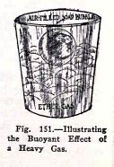
Otto von Guericke, the inventor of the Magdeburg
hemispheres, made a water barometer in 1650, and had it so
arranged that the top of the tube stuck up
through the roof of his house. He had a small wooden figure
floating on the water in the tube and in fine weather, when
the water column rose, the figure rose above the roof, but in
bad weather the figure retired from sight. This frightened and
mystified his neighbors very much and they accused him of
being in league with the evil one.
102 HYDRAULIC AND
PNEUMATIC ENGINEERING
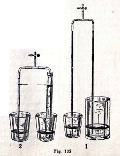
EXPERIMENT No. 48
To show that
the vertical height to which the atmosphere will lift water
in
a tube
is independent of the length or slant of the tube.
Make the experiments (1), (2) and (3), Fig. 134. Suck
air out through the upper coupling on the tee and close the
clip.
Is the vertical height of the water in one tube above
the water in the tumbler always the same as that in the other?
Make experiments of your own.
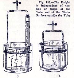
EXPERIMENT No. 49
To show that the height to which the atmosphere will lift
water in a tube is independent
of the size or shape of the tube and of the water surface
outside the tube.
Make the experiments (1), (2), (3) and (4) Fig. 135.
Is the height of the water always the same in the two tubes?
Make experiments of your own.
HYDRAULIC AND PNEUMATIC
ENGINEERING 103
EXPERIMENT No. 50
To show that the atmosphere lifts heavy salt
water to a less height,
and light gasoline to a greater height, than it lifts
fresh water.
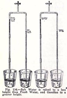
Make the experiments illustrated in Fig. 136.
EXPERIMENT No. 51
To show that the atmosphere will lift weights.
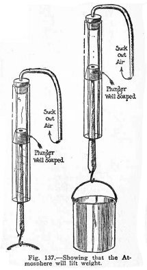
Make the experiments illustrated in Fig. 137.
104 HYDRAULIC AND PNEUMATIC
ENGINEERING
EXPERIMENT No. 52
To show that the atmosphere will lift 15 lbs. per sq.
in. but no more.
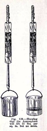
The plungers have an area of 3/10 sq. in. If then, the
atmosphere will lift 15 lbs. on 1 sq. in., it will lift 3/10 x
15 = 4 1/ 2 lbs. on 3/10 sq. in.
Soap the plungers, have water between them but no air,
pour an inch of water above the upper plunger to make it
air-tight, attach a pail weighing less than 4 1/2 lbs. to the
lower plunger, Fig. 138 and raise the upper plunger. Does the
atmosphere lift the lower plunger and weight?
Add water to the pail until the total weight is 4
1/2 lbs. and raise the upper plunger. Do you find that
the atmosphere does not lift the lower plunger? It does not do
so because the atmospheric pressure on 3/10 sq. in. cannot
lift 4 1/2 lbs. and also
overcome the
friction.
Hold the upper plunger and lift the tube. Does the
atmosphere now lift 4 1/2 lbs. weight? It does so because the
friction helps it in this case.
HYDRAULIC AND PNEUMATIC
ENGINEERING 105
Repeat with the water and pail weighing 6 lbs. Do you
find that the atmospheric pressure on 3/10 sq. in. will not
lift 6 lbs. even with the help of the friction.
You have shown here roughly that the atmospheric
pressure on 3/10 sq. in. will lift 4 1/2 lbs. but no more.
This shows that the atmospheric pressure on 1 sq. in. will
lift 4.5 x 10/3 = 15 lbs. but no more.
Make your own experiments.
AIR-LIFT PUMPS
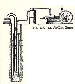
The air-lift pump, Fig. 139, is operated by compressed
air. It consists of two pipes one inside the other, both open
at the bottom and without valves. The pump is at least
half-submerged, that is, the bottom is at least as far below
the surface of the water in the well as the top is above it.
The air which is compressed in the storage tank passes
into the outer pipe of the pump, forces the water down to the
bottom of the inner pipe, and forces the water in the inner
pipe up into the tank. After the first lot of water has been
forced out of the inner pipe the pump settles down to its
regular operation which is as follows. Compressed air from the
outer pipe enters the inner pipe, the pressure in the outer
pipe is thereby lowered and the water rises in the outer pipe
above the bottom of the inner pipe, more compressed air comes
from the tank and forces the water down in the outer pipe but
up in the inner pipe. This operation takes place over and over
again rapidly, and alternate layers of air and water are
forced up the inner pipe as shown in Fig. 139. The water thus
flows from the inner pipe into the tank in spurts as you will
show in your next experiment.
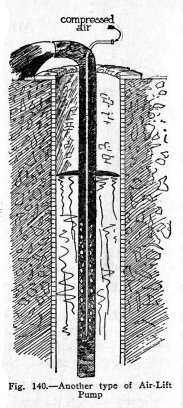
Another form of air-lift pump is illustrated in Fig.
140. Here the air enters through the inner pipe and the
mixture of water and air is
106
HYDRAULIC AND PNEUMATIC ENGINEERING
forced out through the outer pipe. The water comes out
as a continuous heavy spray because the air is mixed with the
water in bubbles rather than in layers.
These are called air-lift pumps but the water is not raised by
the air pressure. It is raised by the weight of the water in
the well outside the pump, because the water rising in the
pump is really a mixture of air and water and is lighter than
a water column of the same height.
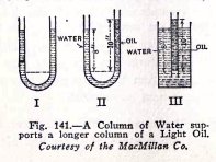
You can illustrate this by means of experiments shown in Fig.
141. In (1) both sides of the U tube are filled with water and
you know from your experiments that the water will be at the
same level in both sides. In (II) one side is filled with
kerosene oil which is only 8/10 as heavy as water, and you
know that a column of water 8 in. high will support a column
of oil 10 in high. Similarly in (III) a depth of water of 8
inches will support a column of oil 10 inches high. If now the
oil in (III) were replaced by a mixture of air and water which
was only 1/2 as heavy as water, you can see that the 8 inch
depth of water would support a column of the mixture 16 inches
high, and so on.
The bottom of the air-lift pump is always placed at
least as far below the sur-
HYDRAULIC AND PNEUMATIC
ENGINEERING 107
face of the water as the top is above, and the water
outside the pump lifts the lighter mixture of air and water to
the top. You will illustrate this in the next experiment.
EXPERIMENT No. 53
To make and
operate two air-lift pumps.
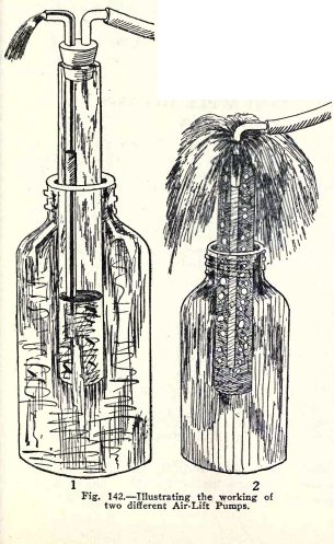
Make an air-lift pump. (1) Fig. 142. Use a quart
sealer to represent the well, fill it to the top with water,
and insert the air-lift pump until it is half submerged, that
is, until the water in the sealer is at a point half way
between the bottom of the wide tube and the top of the elbow
of the discharge pipe.
Force air in through the hose and observe what takes
place near the bottom of the pump.
Do you observe that the water level in the pump moves
alternately down below the end of the discharge pipe and then
up above it, and that alternately water and air are forced up
the discharge pipe?
Do you observe further that when you force air in at
just the right rate the pump works steadily and the
water comes up the discharge pipe in
108 HYDRAULIC AND PNEUMATIC
ENGINEERING
spurts at regular intervals.
In the other type of air-lift pump the compressed air
passes down the inside pipe and the mixed air and water move
up the other pipe.
Make a pump of this kind, (2) Fig. 142 and blow air in
through the inside pipe.
Do you find that air and water are forced up over the
top of the outside pipe?
Repeat the experiment with the pump deeper in the
water.
Do you find that it works better the deeper it is in
the water?
LAWS WHICH
APPLY TO GASES
PASCAL'S LAW
In the remaining pages of this book you will study
three laws which apply to gases and you will illustrate many
practical applications of these laws. They are Pascal's law,
Archimedes' law, and Boyle's law. You will begin with Pascal's
law.
You learned on pages 49, 50 and 51, Pascal's law which
states one property of liquids; namely, pressure exerted on a
liquid is transmitted by the liquid equally and undiminished
in all directions. This law also states a property of gases as
follows: pressure applied to
a gas is transmitted
by the gas equally and undiminished in all directions.
You are very familiar with one application of this
law, namely in the pneumatic tire. The air in a bicycle or
automobile tire exerts pressure outward equally at every part
of the tire.
EXPERIMENT No. 54
To illustrate Pascal's law as it applies to gases.
Shove the plunger in (1) Fig. 143, down, and feel the
air at the nozzles. Are the pressures equal?
Blow a soap bubble (2). Is it a perfect sphere? This
shows that the air exerts pressure equally in all directions
against the inside of the bubble.
Make a three legged siphon filled with air (3), place
two legs in tumblers of water, place the third leg in the wide
tube partly filled with water, and raise and lower the wide
tube.
HYDRAULIC AND PNEUMATIC
ENGINEERING 109
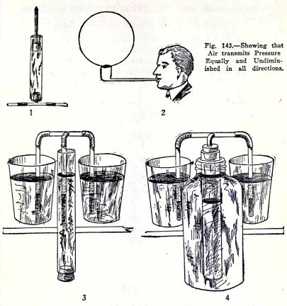
The water in the wide tube exerts pressure on the air
in the third leg. Is this pressure exerted equally and
undiminUhed by the air, that is, is the water level in the
three legs always at the same distance below the water
outside?
Repeat this with the apparatus (4). Is the result the
same?
You have here proved Pascal's law, namely that a gas
transmits pressure equally and undiminished in all directions.
110 HYDRAULIC AND
PNEUMATIC ENGINEERING
BALLOONS AND
THE BUOYANT FORCE OF AIR
The Law of Archimedes applied to Gases
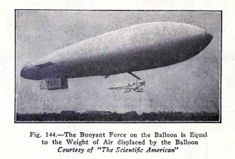
Balloons float in air and this fact is due to a
property of air which is expressed by the law of Archimedes.
You have already made experiments on this law with
liquids and you have shown that t
he buoyant force of a liquid on a body is equal to
the weight of the
liquid displaced by the body. This is the
law of Archimedes as it applies to
liquids.
The
law of
Archimedes in regard to gases is: t
he buoyant force of a gas on a body is equal to the
weight of the gas displaced by the body.
How the Total Lift of a Balloon is Calculated
The weight of air is about 1 1/4 ounces per cubic foot
at ordinary temperatures and at the surface of the earth. If
then a balloon displaces 1,000,000 cubic feet of air, its
total lift or buoyancy is 5/4 x 1,000,000 = 1,250,000 ounces =
1,250,000/16 lbs. = 78,125 lbs. and so on. The useful load a
balloon can lift is its total lift minus the weight of the
envelope, of the gas in the envelope, of the cars, of the
engines, and of the fuel.
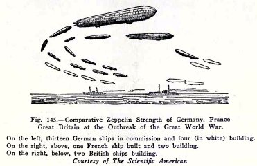
In Fig. 145 we show the relative strengths in
dirigible balloons of Germany, France and Great Britain at the
beginning of the war. Britain
HYDRAULIC
AND PNEUMATIC ENGINEERING 111
and France built many dirigibles during the war and
one of the latest built by Britain displaces 1,600,000 cubic
feet of air. Its total lift therefore is 1,600,000/16 x 5/4 =
125,000 lbs.
The balloon is filled with hydrogen which weighs about
1/14 as much as air, and therefore 1/14 of the total lift is
used up in lifting the hydrogen gas. The weight of the
hydrogen is 125,000/14 = 8928 lbs.
Hydrogen gas has been used in balloons because it is
the lightest gas known. It has one great drawback, however, in
that it burns very readily. There is another gas called helium
which is twice as heavy as hydrogen but which has the great
advantage that it does not burn.
Before the war helium was very expensive but during
the war it was found that the helium which occurs in some of
the natural gases of the United States could be separated at a
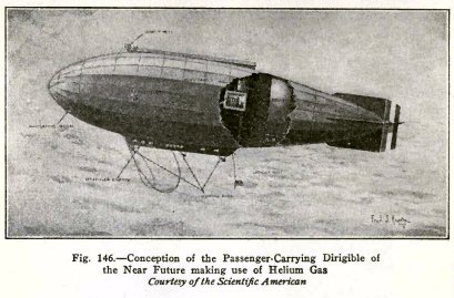
reasonable cost. It is expected that the dirigibles of the
future will be filled with helium, and since it does not burn,
it will be possible to put the engines in a room inside the
balloon as shown in Fig. 146.
112
HYDRAULIC AND PNEUMATIC ENGINEERING
Although helium is twice as heavy as hydrogen its
lifting power is only 1/13 less because the lift of a balloon
depends primarily on the weight of air displaced. You can show
this as follows :
If a balloon displaces 140,000 lbs. of air and it is
filled with hydrogen, it holds 140,000/14 = 10,000 lbs. of
hydrogen, since hydrogen weighs 1/14 as much as air.
If the balloon is filled with helium it holds
140,000/7 = 20,000 lbs. of helium, since helium weighs 1/7 as
much as air.
The lift minus the weight of hydrogen = 140,000 -
10,000 = 130,000 lbs.
The lift minus the weight of helium = 140,000 - 20,000
= 120,000 lbs.
That is, the lift with helium is only 1/13 less.
EXPERIMENT No. 55
To illustrate the buoyant force of air.
Blow a soap bubble with illuminating gas (1) Fig. 147.
Does the bubble rise?
HYDRAULIC AND PNEUMATIC
ENGINEERING 113
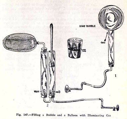
Blow up a balloon with illuminating gas by means of
the force pump (2) Fig. 147. Does the balloon rise?
The bubble and balloon rise because they displace a
greater weight of air than their own weight plus the weight of
the gas in them.
EXPERIMENT No. 56
To illustrate the buoyant force of air by means of a
balloon filled with hydrogen.
114 HYDRAULIC AND PNEUMATIC
ENGINEERING
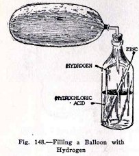
If the metal zinc is placed in an acid, the metal is
dissolved by the acid and hydrogen gas is produced. You can
make hydrogen gas and fill the large balloon with it as
follows.
Purchase at a drug store 2 ounces of strong
hydrochloric acid (also called muriatic acid) which should
cost about 5 or 10 cents; also purchase at an electrical shop
a zinc rod for a Leclanché battery, which will also cost about
5 or 10 cents, or purchase two zinc strips.
Pour the acid into the bottle and add an equal volume
of water. This dilutes the acid and slows up the production of
the hydrogen. If the hydrogen is produced too fast it will
bubble acid up into the balloon.
Now to make hydrogen and to fill the balloon, proceed as
follows: Arrange the bottle as shown in Fig. 148 and attach
the large balloon to the elbow by means of a short piece
(about 1 1/2 in.) of a
stretched
rubber
band. When you have done this place the zinc rod or
zinc strips gently in the bottle, insert the stopper at once,
and allow the hydrogen to fill the balloon. It will take about
5 minutes to fill the large balloon completely.
When the balloon floats well in the air, slip it off
the elbow with its
stretched
rubber band. The band will contract and close the
balloon.
Now release the balloon. Do you find that it floats up
to the ceiling?
Precautions.
Be very careful not to get any of the acid on your hands or
clothes. It will burn very bad holes if it does.
When you are through empty out the liquid left in the
bottle, as it is of no further use, and rinse the bottle and
rod very thoroughly with water.
You must not use the zinc in small pieces because it
produces the hydrogen too fast and makes the acid bubble up
into the balloon. Use the zinc in the shape of a rod or
strips.
HYDRAULIC AND PNEUMATIC
ENGINEERING 115
EXPERIMENT No. 57
To shoot down a balloon.
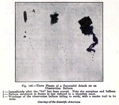
We show in Fig. 149 three views of a balloon shot down
by means of incendiary bullets. These bullets set the hydrogen
on fire, the envelope burns, and the car and machinery fall to
the ground.
A toy balloon filled with hydrogen as in the last
experiment floats up to the ceiling. It will come down by
itself in a few hours because the hydrogen
gradually passes out through the rubber.
If you are in a hurry to get the balloon down, and if
you have an air rifle, you can shoot a hole through the
balloon: the hydrogen will then escape and the balloon will
fall at once. This method, however, spoils the balloon.
116 HYDRAULIC AND PNEUMATIC
ENGINEERING
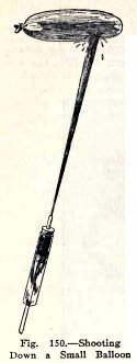
You can shoot the balloon down with a syringe without
destroying it as shown in Fig. 150. The water on the balloon
will make its weight greater than the buoyancy of the air
displaced by the balloon and this will bring it down.
If you let the water evaporate, the balloon will rise
again because it again becomes lighter than the air it
displaces. You can then shoot it down again with water.
EXPERIMENT No. 58
To illustrate the buoyant force of a gas heavier than
air by means of a soap bubble filled with air.
Purchase at a drug store one ounce of ether and pour
it into an empty 12 qt. pail, cover the pail with a newspaper
and allow it to stand for about 10 minutes.
The ether will evaporate and produce ether gas. This
being heavier than air will remain in the bottom of the pail
and force the lighter air out at the top.
Now dip the end of the wide tube in the soap suds and
shake off the excess soapy water. Blow a large bubble and
detach it about 6 in. above the bottom of the pail.
Do you find that the soap bubble filled with air
floats on the heavy ether gas?
The buoyant force of the ether gas is the weight of
this gas displaced by the bubble. This buoyant force is
sufficient to support the soap bubble film and the air inside
of it.
HYDRAULIC AND PNEUMATIC
ENGINEERING 117
COMPRESSED AND EXPANDED GASES
BOYLE'S LAW
You will now illustrate Boyle's law and then make a
number of appliances which make use of this law, namely, the
air brake, flame thrower, fire extinguisher, air pump, bicycle
pump, sand blast, pneumatic paint brush, diving bell,
pneumatic caisson, and submarine air supply.
Boyle's law is:
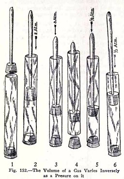
The
volume of a gas varies inversely as the pressure on it.
This is illustrated in Fig. 152. In (1) the tube is full of
air and the pressure on the air is one atmosphere because the
tube is open to the atmosphere. In (2) the pressure on the air
is 2 atmospheres and the volume of the air is 1/2 what it was
in (1). In (3) the pressure on the air is 3 atmospheres and
1/3 what is was in (1) and so on.
In (4) the air in the tube below the plunger is under
1 atmosphere pressure because the tube is open to the
atmosphere. In (5) the tube is closed, the plunger is raised
until the pressure on the air is 1/2 atmosphere and its volume
is two times what it was in (4). In (6) the plunger is raised
until the pressure on the air . in only 1/3 and its volume is
three times what it was in (4).
These illustrate Boyle's law.
118 HYDRAULIC AND PNEUMATIC
ENGINEERING
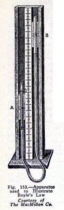
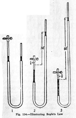
Boyle's law is usually illustrated by means of the
apparatus shown in Fig. 153. The glass tube A is closed at the
top and is partly filled with air, the second glass tube B is
open at the top, and the two tubes are connected by a rubber
tube filled with mercury.
The mercury surfaces at the beginning are at the same
level, (1) Fig. 154, and since the pressure on the mercury
surface in B is 1 atmosphere, the pressure on the air in A is
also 1 atmosphere.
If now B is raised until its mercury surface is 30 in.
above that in A, the air in A is under 2 atmospheres pressure
and it is compressed to 1/2 its first volume, (2).
If B is raised until its mercury surface is 60 in.
above that in A, the air in A is under 3 atmospheres pressure
and it is compressed to 1/3 its first volume (3), and so on.
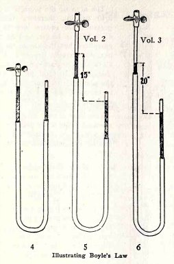
If on the other hand, B is lowered, (5), until its mercury
surface is 15 in.
HYDRAULIC AND PNEUMATIC ENGINEERING 119
below that in A, the air in A is under a pressure of
only 1/2 atmosphere and it expands until its volume is 2 times
its volume in (4).
If B is lowered (6) until its mercury surface is 20
in. below that in A, the air in A is under a pressure of only
1/3 atmosphere and it expands until its volume is 3 times its
volume in (4), and so on.
Note: A
column of mercury 30 inches high exerts a pressure equal to
that of one atmosphere. Similarly 15 in. = 1/2 atmosphere and
10 in. = 1/3 atmosphere.
EXPERIMENT No. 59
To illustrate Boyle's law.
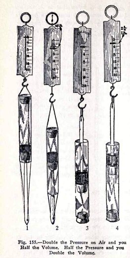
If you have a spring balance you can prove Boyle's law
as follows: Use the apparatus (1) Fig. 155 and compress the
air to one half its volume as in (2). Is the average pull on
the balance 4 1/2 lbs.?
Note: Friction
opposes the plunger when it is moving in, but it helps the
plunger to remain in. You will find that it takes more than 4
1/2 lbs. to compress the gas, but less than 4 1/2 lbs. to hold
it after it is compressed, the average is 4 l /2 lbs.
120 HYDRAULIC AND PNEUMATIC
ENGINEERING
The area of the plunger is 3/10 sq. in., therefore the
pressure per square inch is 4.5 x 10/3 = 15 lbs. or 1
atmosphere, but the air on the outside exerts a pressure of 1
atmosphere on the plunger, therefore the total pressure the
plunger exerts on the air in the tube is 1 + 1 = 2
atmospheres.
You have shown here that when you double the pressure
on a gas you compress the gas to one half its first volume.
To show that when you halve the pressure on a gas its
volume doubles, use the apparatus (3) Fig. 155.
Start with a distance of 2 inches between the
plungers, (3) then pull up the spring balance until the
distance is 4 inches, (4). Is the average pull on the balance
2 1/4 lbs.?
A pull of 2 1/4 lbs. on 3/10 sq. in. is 2.25 x 10/3 =
7.5 lbs. per sq. in. or 1/2 atmosphere. Since the pull of the
balance is only 1/2 atmosphere, the air in the tube must be
exerting the other 1/2 atmosphere.
HYDRAULIC AND PNEUMATIC
ENGINEERING 121
THE AIR BRAKE
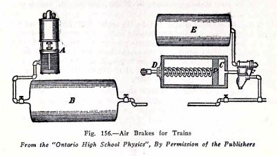
One of the commonest applications of compressed air is
in the air brakes on trains. The air compressor A, on the side
of the engine boiler, is operated by steam from the boiler. It
compresses air in the large tank B, on the locomotive, and
this compressed air is carried through the train pipe under
the cars to the air brake under each car. The air brake on
each car consists of a triple valve F, an air tank E and a
cylinder C containing a piston P. The brake beam is attached
to D.
The operation of the air brakes is as follows: Air is
pumped into the locomotive tank B until its pressure is about
75 tbs. per sq. in. This compressed air moves through the
train pipe, through the triple valve F, and into the car tanks
E.
When the train is running, the pressure in each car
tank E is equal to that in the locomotive tank B ; but there
is no air in the cylinder C and the brakes are "off", because
the spring holds the piston P in the position shown.
When the engineer puts "on" the brakes, he turns a
lever which closes the valve between B and the train pipe, and
which at the same time, lets the air out of the train pipe.
When the air pressure in the train pipe
122 HYDRAULIC AND PNEUMATIC
ENGINEERING
decreases, the triple valve shifts in such a way that
compressed air passes from the tank E into the cylinder C;
this compressed air drives the piston out with a pressure of
75 lbs. per sq. in. and puts the brakes "on."
When the engineer wishes to take the brakes "off"
again, he turns the lever back. This closes the train pipe and
at the same time allows air to flow from tank B through the
train pipe to the triple valve F. When the pressure in the
trian pipe increases, the triple valve shifts back in such a
way that it lets air pass from B into E, also it closes the
passage from E to C, and lets the air out of C. The spring
then forces the plunger in and takes the brakes "off".
It will be noticed that if the train should break in
two by the breaking of a coupling, the rubber air hose
connection on the train pipe is broken and the air is let out
of the train pipe. This automatically sets the brakes on each
car and both parts of the train are brought to a standstill.
You will now make and operate an air brake and
illustrate the working of the cylinder, triple valve, and air
tank.
EXPERIMENT No. 60
To make and operate an air brake and to illustrate the
working
of
the triple valve,
cylinder, air tank, and train pipe.
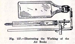
Use the apparatus as shown in Fig. 157, open clip 1,
and blow air into the rubber tube.
Your mouth here represents the compressor and air tank
on the locomotive, and while you are blowing air into the tank
E you are representing the conditions when the train is
running and the brakes are "off". You will notice here that
when clip 1 is open and 2 is closed the triple valve is
admitting air to the tank E, the cylinder C is open, and the
brakes are "off". Clips 1 and 2 represent the triple valve.
Now close clip 1 and open clip 2. Do you observe that the
compressed air in E forces the piston out? This is exactly
what happens when the
HYDRAULIC AND PNEUMATIC
ENGINEERING 123
engineer puts the brakes "on". You will notice here
that when clip 1 is closed and 2 is opened, the triple valve
has closed the passage between the cylinder and train pipe,
and has opened the pipe between E and the cylinder. This is
the condition when the brakes are "on".
If you have a bicycle pump, use it instead of your
mouth and pump more air into the tank E. You will then find
that the piston is driven out with greater force.
At the next opportunity examine the air brakes under a
box car or flat car on a railway siding. Identify the air
tank, cylinder, piston rod end, the triple valve, and the
train pipe. Notice that the outward movement of the piston
rod, moves a lever, and that this lever in turn sets the
brakes.
THE FLAME THROWER
You have read of the flame throwers, which were used
during the war. You will illustrate their action in the next
experiment.
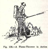
A flame thrower is a strong metal tank with a pipe and
nozzle leading from the bottom. It contains a mixture of
inflammable oils in the lower part and above this, hydrogen
gas under great pressure.
The tank is carried on the back of the soldier, as
shown in Fig. 158, and when the nozzle is opened the
compressed hydrogen drives the oil out with great force. The
oil is set on fire by a pilot light just beneath the nozzle
and the moving stream becomes a stream of flame or liquid
fire.
124 HYDRAULIC AND
PNEUMATIC ENGINEERING
EXPERIMENT No. 61
To illustrate the action of the flame thrower.
It is dangerous to illustrate the action of a flame
thrower with oil and you will use water instead.
Arrange the apparatus as shown in Fig. 159. To load
the flame thrower, place a clip on the rubber tube, put a
stopper and elbow on the end, insert the stopper into a water
faucet, open the faucet gently, open the clip, and allow water
to enter the bottle until it is one half full, then close the
clip.
The flame thrower is now loaded; the water represents
the oil and the compressed air represents the compressed
hydrogen.
Now to use the flame thrower; replace the elbow and
stopper at the end of the rubber tube by a nozzle, turn the
bottle upside down, point the nozzle at the thing you wish to
hit, and open the clip.
THE FIRE EXTINGUISHER
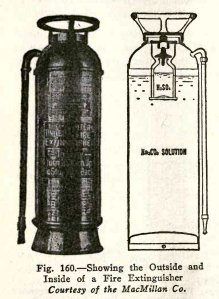
The common household fire extinguisher, Fig. 160, is a
strong brass cylinder with a short piece of hose attached at
the top; this hose and its nozzle are open at all times. The
extinguisher is charged as follows: In the bottom there is a
solution of 1 1/2 lbs. of sodium carbonate (Na2CO3)
and 2 l/2 gal. of water, and above this there is an 8
oz. bottle containing 4 ozs. of strong sulphuric acid (H2SO4).
This bottle is fitted with a loose lead stopper which falls
out when the extinguisher is turned upside down.
To use the extinguisher, you carry it right side up to the fire,
then turn it upside down
and direct the stream of water and gas upon the fire by
means of the short hose. Use all of the water, because
once you have turned the extinguisher upside down, the liquids
are mixed, and the extinguisher is of no further use until you
have re-
HYDRAULIC AND PNEUMATIC
ENGINEERING 125
charged it. You should do this at once in order to be
prepared again for a fire. In recharging you should follow the
directions printed on the case.
The action which takes place in the extinguisher is as
follows: when you turn it upside down, the sulphuric acid and
sodium carbonate react chemically and produce a large quantity
of carbon dioxide gas. The volume of carbon dioxide gas
produced is much greater than the volume of the cylinder and
therefore the gas exerts pressure on the water and drives it
out with great force.
The fire is extinguished, partly by the water, and
partly by the gas. It seems strange to speak of putting out a
fire by means of gas, but carbon dioxide gas has three
properties which make it very valuable for this purpose:
first, it does not burn; second, it does not support
combustion, that is, it does not help other things to burn;
third, it is heavier than air. The carbon dioxide gas
surrounds the fire and smothers it, because it does not
support combustion and it takes the place of the air
which does support combustion.
EXPERIMENT No. 62
To make and operate a fire extinguisher.
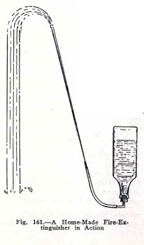
You will not use strong
sulphuric acid because it burns practically everything it
touches, but instead you will use a dilute acid, vinegar; also
you will use baking soda which is sodium carbonate. Arrange
the apparatus as shown in Fig. 161. Pour six tablespoonsful of
vinegar into the bottle, fill the bottle four fifths full of
water and shake, measure out one level tablespoonful of baking
soda and place it on a piece of paper ready for use.
Now to use the fire extinguisher, go outside and let
one experimenter hold the bottle and stopper while the other
holds the baking soda and the nozzle. Dump the soda into the
bottle, put in the stopper quickly and hold it very
 The
Science Notebook
The
Science Notebook