 The
Science Notebook
The
Science NotebookSimple Machines - Part 1
The
Science NotebookHome Terms of Use Safety Contact Us Experiment Pages Downloads Supplies Useful Links!
In our everyday life, we usually think of work as
something we have to do. We have to read tomorrow’s
social studies assignment, do some math problems, or mow the
lawn. If it is something we have to do, or something that
keeps us from doing what we want to do, we call it
“work”.
But to the scientist, work
means using energy to move an object from one place to
another. When you pick up a book, you do work. When
you ride a bike from your house to visit a friend, you use
the bike to do work. When you play baseball, you are doing
work as well. If you are moving yourself or anything
else, you are doing work.
By this definition, we do
lots of work every day, and much of that work is made easier
by the use of machines. When we think of machines, we
usually think of large pieces of equipment which perform
specific tasks like washing machines or lawn mowers. But if
you look closely at most any complex machine, you will find
that it uses one or more of six simple machines, along with
something that provides energy to operate the machine.
These six machines are the
lever, the wheel and axle, the pulley, the inclined plane,
the screw, and the wedge. Each of these machines is
capable of making work much easier to do, and when each is
used by itself, or when one or more are combined together,
they perform many of the tasks that we take for granted
every day.
In this chapter, we will
explore the six types of simple machines, and we will see
how each makes work easier. We will also see that
while machines make the work easier to do, they really don’t
decrease the amount of work required.
A lever is a very simple device that consists of a
rigid length of wood, metal or other solid material which
pivots on a point called the fulcrum. At some point on
one side of the fulcrum, there is a weight or load to be
moved which is called the resistance. At another point on
the lever, a force is applied to move that weigh called the
effort.
There are three types, or
classes, of lever - first class, second class, and third
class. The class of the lever is determined by where the
fulcrum is located in relation to the resistance and the
effort.
The see saw is a simple first class lever.
The fulcrum of this lever is the pivot point at the center
of the see saw. In this experiment, the resistance
will be the weight of the person you will try to lift.
The effort will be the force you apply to lift that
person. This is a first class lever because the
resistance is on one side of the fulcrum, and the effort is
on the other side.
Materials Needed: A
playground see saw; a friend who weighs about the same as you.
Procedure: If
the see saw can be moved, make sure that it is centered.
Have your friend to sit on one end of the see saw while you
push down on the other end. When you push your end all
the way to the ground, notice the distance from the part of
the see saw under your friend to the ground.
Carefully lower your friend and have him or her to move half
way between the end of the see saw and the middle. Now
push down on your end to lift your friend. Do you have
to push easier, harder, or about the same, to lift your
friend? Observe how far he or she is from the ground directly
underneath.
Now, have your friend to return to the end of the see
saw. Push down at a point half way between your end and
the middle of the see saw to lift your friend. This
time, do you have to push easier, harder, or about the same?
What Happened: The
first time you lifted your friend, you were able to lift him
or her by applying a force that was roughly equal to his or
her weight. It was probably fairly hard to do (unless
you cheated and put your weight on the see saw...).
When your friend moved closer to the fulcrum, or pivot point,
you probably found your friend much easier to lift.
However, if you observed carefully, you should have noticed
that you did not lift your friend as high as before, because
the lever was closer to the ground at the point where your
friend was sitting when you pushed your end all the way
down. You didn’t have to apply as much effort as before,
but you weren’t able move your friend as far, either.
When you moved closer to the fulcrum, you probably noticed
that it was much harder to lift your friend from that point,
but you didn’t have to move the see saw as far as you did when
you were at the end. In this case, you had to apply much
more effort to lift your friend, but you didn’t have to apply
that effort through as great a distance.
One advantage of a lever is
that it allows you to move much more weight than you could
otherwise move without the lever. But can we measure
just how much effort is saved, and what, if anything, we
have to give up to save it? We can, but before we do,
we are going to have to make a couple of simple pieces of
equipment.
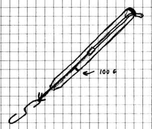
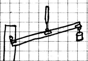
When we study simple machines, we need to be able
to weigh a given object and to measure how much effort is
required to lift it. To do this, we will need some
sort of force indicator such as the one shown below, or a
spring scale. You may be able to borrow a spring scale
from your school science lab if one is available. If
not, you can make this one to use in your study of simple
machines. The instructions given here will allow you
to make one that will allow you to see whether a particular
force is greater or less than 100 grams. By changing
the size of the rubber band, you can make one that will
allow you to observe larger or smaller forces.
Materials Needed: Old
Bic® or similar pen with a clear barrel (It does not have to
be able to write); pliers; scissors; rubber band; string;
tape; paper clip; permanent marker; 35 mm film canister or
similar small container; homemade
balance or other scale (see procedure); sand or powdered
iron.
Procedure: Begin by
placing the film can and lid on the balance or scale.
Add sand or powdered iron to the can until the total weight of
the can, lid and iron or sand is 100 grams. Label the
can “100 g” and set it aside. (You can use the homemade
balance, so long as you have 100 grams of weights. If you
didn’t make one, you can use a triple beam balance at school
with the help of a teacher, or a small home “diet” scale that
will weigh 100 grams.)
You may need to get an adult to help you with this step. Using
a pair of pliers, pull the pen point and ink tube from the
barrel of the pen. Throw it away. Then, remove the
plastic piece from the top of barrel and save it.
Cut a rubber band to make a long strip of rubber. Tie a
30 cm (12 in) string to one end and place a small piece of
tape around the knot. Trim any excess string and rubber
band sticking out from the tape. Run the string and the
rubber band through the top of the barrel (string first) until
the rubber band is about one fourth of the way down the
barrel. Place the plastic piece from the top back in the
barrel to hold the rubber band in place. Bend a paper
clip into an “S” shape and tie it to the other end of the
string.
Next, tie a small loop of string and place part of the loop
inside the film can. Snap the lid into place. Lift
the barrel of the pen up and hang the 100 g weight you have
just made onto the paper clip. Hold the pen so that the
film can weight is suspended underneath. You want the rubber
band to stretch to about halfway to the bottom of the pen
barrel. If it stretches farther than that, take the
plastic top off of the barrel, and adjust the rubber band so
that it goes half way to the bottom. If the rubber band
doesn’t stretch that far, you may need to try a thinner or
longer rubber band. If the rubber band stretches too
far, then you may need to try a shorter or thicker rubber
band. You may have to try several before you find one that
works.
You will need to calibrate your force indicator by making a
mark on the pen barrel with the permanent marker beside the
end of the rubber band when the 100 gram weight is suspended
from the scale.
Your indicator is now ready to use for some experiments with
simple machines.
Going Further: As you
can see, this rubber band force indicator is actually a very
simple scale which will measure 100 grams when it is even with
the mark. If an object suspended from the pen stretches
below that mark, it weighs more than 100 grams, and if the
rubber band does not stretch that far, the weight is less than
100 grams.
If you hold the barrel of the pen and pull down on the paper
clip, you can see that this may also be used to measure
force. If less than 100 grams of force is required, then
the end of the rubber band will be somewhere above the mark on
the barrel. If you pull on the clip with more than 100
grams of force, then the end of the rubber band will go below
the 100 gram mark.
This next experiment will
show you how to build a lever that you can use to
investigate the properties of all three classes of
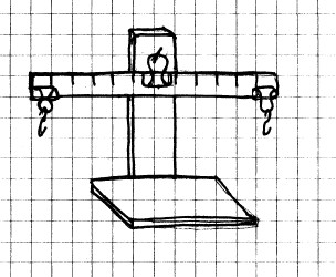
levers. If you have built the homemade
balance, you already
have most of the work done, since the base of the balance is
basically the same as the lever support you make here, and
can be used in its place.
Materials Needed: Two
small boards about 30 cm (12 in) long and 7-10 cm (3-4 in)
wide. (Exact sizes aren’t too important. You can
probably use whatever you have on hand.); three small nails;
ruler, meter stick or yard stick; three small binder clips;
two paper clips; meter stick; pen or pencil.
Procedure:
Nail one of the boards to the other as shown below. Use
two nails so that the boards will not slip. Nail the
third nail about an inch or so from the top of the upright
board. This will be used for the lever support.
Clip one of the binder clips on the center of your ruler or
measuring stick. Clip the other two clips at each end
opposite to the middle clip. Now hang the wire handles
of the middle clip on the nail in the upright board. If
this one doesn’t exactly balance with the clip in the middle,
adjust the middle clip to balance the two sides.
Bend the two paper clips to make “S” shaped hangers.
These will be used later.
Your lever is now ready to use for the following experiments.
You should remember that a
first class lever is one that has the fulcrum between the
weight and the effort. The see saw is one practical
example of a first class lever. Two others are a crow
bar and the claw end of a hammer used to remove nails.
Up to this point, we have
seen how a first class lever works to make loads easier to
lift. With a spring scale or the force indicator, we
can measure just how much easier.
Materials Needed: 100
gram weight; laboratory lever; homemade force indicator or
spring scale (may be borrowed from school).
Procedure: You should
have binder clips on the lever at each end. The clip
that is your fulcrum should be balanced on the support.
Hang the 100 g weight from one of the binder clips (the
resistance clip). Hook your homemade force indicator or
spring scale to the other clip (the effort clip) and pull
downward to lift the weight. If you are using the force
indicator, where is the rubber band? If you are using a
spring scale, what is the reading on your scale?
Next, move the resistance clip about half way from the end to
the fulcrum. Again, pull down on the effort clip with
the scale. Is more or less force required? If you
are using a spring scale, can you tell how much force is
required now?
Now return the resistance clip to the end and move the effort
clip so that it is halfway from the end to the fulcrum.
Again pull down with the force indicator or scale. How
much force is required now?
What Happened: You
already know from the see saw experiment that the fulcrum is
between the resistance and the effort in a first class
lever. There, you saw that as your friend moved close to
the fulcrum or center, it was easier for you to lift him or
her (required less effort), but you also saw that the closer
your friend moved to the center, the less high he or she was
lifted.
You should have seen the same thing here. When the
effort and the resistance were the same distance from the end,
the effort should have equaled about 100 g. As you moved the
weight closer to the center, the effort required was less than
100 g. However, when you moved the effort end closer to
the fulcrum, more than 100 g of effort was required.
Going Further: If you
are using a spring scale, try changing the distance between
the fulcrum, resistance and effort. Use your spring
scale to determine exactly how much effort is required at the
different distances. Also, does the weight of the lever
itself make a difference when you move the fulcrum? Why
or why not? For the time being, make sure that the resistance
and effort are on opposite sides so that you continue to have
a first class lever.
When simple a machine, such as a lever, takes a
small force (or effort) and increases the effectiveness of
that force, a mechanical advantage has been produced. For
example, a lever may require a force of only 50 g to lift
100 g. If so, it has a mechanical advantage of 2,
because it doubles the effectiveness of the 50 g
effort. While the rubber band force indicator may give
you some idea of how much the mechanical advantage
increases, a laboratory spring scale borrowed from school
will help you to see this much better.
Materials Needed:
Laboratory lever; rock or other small weight; laboratory
spring scale.
Procedure: Weigh
the rock (or other weight) and record the weight.
Set up your lever so that the fulcrum is in the middle, and
the weight and effort are at opposite ends an equal distance
from the fulcrum. Use the spring scale to measure the
effort needed to lift the weight. It should be about equal to
the weight. You can use the following formula to
calculate mechanical advantage:
Suppose your weight is 200 g and the spring scale reads 200 g
when you pull down. Then,
Now move your weight half way to the fulcrum ad measure the
effort needed to lift it. Suppose the effort is now
measured at 100 g. Now,
Depending on you measurements, the mechanical advantage of
your lever will be different, but your answer should be
greater than 1. Calculate the mechanical advantage using
your numbers.
Now return the weight to where it was and move your effort
halfway to the fulcrum. Measure the effort needed to
lift the weight now. Suppose it is now 200 g.
(Again, it probably won’t be exactly this, but it should now
be more than the weight.) Now,
Calculate the new mechanical advantage using your
numbers. In the example above the mechanical advantage
is 1/2. Your answer may vary, but it should now be less than
1.
What Happened: A
mechanical advantage of 1 means that the load is no easier or
harder to lift with the lever than without it. If the
mechanical advantage is more than 1, the lever (or other
machine) will make a load easier to lift. However, it
the mechanical advantage is less than 1, the load is harder to
lift than it would be without the lever.
Going Further: If you
understand how to calculate mechanical advantage, try changing
the distances of the fulcrum, resistance and effort, and
calculate the mechanical advantage.
There is one more bit of math we need to know about
levers, but it isn’t hard at all. In any lever, the
distance of the resistance (or weight) from the fulcrum
times the resistance will always equal the distance of the
effort from the fulcrum times the effort. This can be
written:
Let’s see how this works.
Materials Needed:
Setup from the last experiment.
Procedure: Repeat the
last experiment, first with the resistance (weight) and the
effort the same distance from the fulcrum, then with the
weight halfway from the end to the fulcrum, and finally, with
the effort halfway from the end to the fulcrum.
At each position, measure the distances from the fulcrum to
the resistance and to the effort. You can use either cm
or in.
Using these numbers and the formula above, see if the numbers
really are equal. For example, suppose the weight is 100
grams and is 10 cm from the fulcrum, while the effort is 25 cm
from the fulcrum, and is 40 g.
What Happened: Your
numbers may not be exactly equal, but they should be fairly
close. The reason they may not be exactly the same
include errors in measuring the length from the fulcrum to the
effort and resistance, and errors in measuring the weight and
effort (due to the accuracy of the scales). However, the
numbers may also not be exactly the same because of something
else that has to be considered that may be difficult for you
to measure. The weight that is being lifted includes not only
the weight itself, but the weight of the resistance arm, as
well. If that is difficult to imagine, think of how your
lever would be different if the lever were made of a piece of
iron instead of wood or plastic. Then the lever arm
would probably weigh much more than the 100 gram weight, and
it would definitely affect your measurements.
A second class lever is one
that has the resistance (weight) between the fulcrum and the
effort. An example of a second class lever is the
wheelbarrow. The fulcrum is the wheel, the effort
point is at the handle, and the resistance or weight is
between the two. If you have ever used a wheelbarrow, you
know that it makes a load much easier to lift. Let’s see
why.
Materials Needed:
Laboratory lever; spring scale; 100 gram weight.
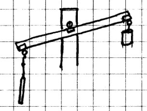
Procedure: Set up
the lever with clips on each end of the lever and the third
clip in the middle. This time, the two end clips should
be on the same side, as shown.
Place one end on the nail. This will be the
fulcrum. Hang the 100 g weight from the middle, and use
your spring scale to lift the other end. How much effort
is required to lift the weight?
What Happened: In this
second class lever, the effort required to lift the weight was
less than the weight, but notice that you had to lift the end
of the lever much higher than the weight was lifted.
A third class lever is one that has the effort
between the fulcrum and the resistance (weight). An
example of a third class lever is your forearm. The
fulcrum is your elbow, the effort point is where your muscle
attaches to the bone of your forearm, and the resistance or
weight is at the end in your hand. As you will see,
there is no mechanical advantage gained with this type of
lever, since the mechanical advantage will always be less
than one. However, this type of lever still has some
practical uses.
Materials Needed:
Laboratory lever; spring scale or homemade force indicator;
100 gram weight.
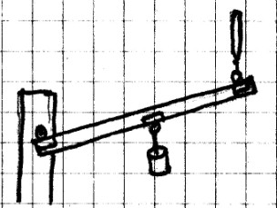
Procedure: Set up
the lever as in the previous experiment with two clips on each
end of the lever and the third clip in the middle as
shown.
Place one end on the nail. This will be the
fulcrum. Hang the 100 g weight from the other end, and
use your spring scale to lift the middle. How much
effort is required to lift the weight?
What Happened: In this
third class lever, the effort required to lift the weight was
greater than the weight itself. However, you should have
seen that the weight moved a greater distance than the
effort. There is no mechanical advantage here,
since greater effort is required to lift the weight, but if
the force is available to do the work, then the weight may be
moved a much greater distance. This is the principle
behind many large cranes.
You may already know that wheels can reduce
friction, but did you know they can be used as simple
machines as well? It is possible to connect two wheels
together by a belt, a chain, or by gears to either gain a
mechanical advantage, or to else to gain additional
speed. Such wheel and axle combinations can be seen in
devices such as bicycles, mechanical clocks and watches, and
some parts of a car engine, just to name a few.
Materials
Needed: Corrugated cardboard; compass; scissors;
tape; pencil with an eraser; straight pin; string; 100 g
weight; force indicator or spring scale.
CAUTION! Always use sharp
objects such as knives or scissors with adult supervision
only! Hold any sharp point away from your body,
particularly your eyes.
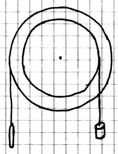
Procedure: Draw a
circle with a 15 cm (6 in) radius and another with a 8 cm (3
in) radius on the cardboard. Cut out the two
circles. Using the sides of the scissors, go around the
edge of each circle and press down on the middle layer of
cardboard. You want to make a thin groove all the way around
each circle.
Line up the centers of the two circles and tape them together.
Carefully punch a hole in the center of the circles just large
enough for the pencil to go through. Push the pencil
through the hole. The two circles should be able to turn
easily on the pencil, but they should not be too loose.
Tape a 1 meter piece of string to the edge of the large circle
and wrap three or four turns around it. Leave about 20
cm free. Tape another piece of string to the edge of the
small circle. Wind three or four turns around the small circle
in the opposite direction.
Tape the pencil to the edge of a table with the circles
hanging over the edge.
Attach the 100 g weight to the end of the string on the small
circle, and the force indicator or spring scale to the end of
the string from the large circle. Pull down on the
string from the large circle and note how much effort is
required to lift the weight.
Next, attach the weight to the string on the larger circle and
the scale or force indicator to the string on the smaller
one. Again, lift the weight and see how much force is
required now.
What Happened: When
you first attempted to lift the weight, the effort required
was less than 100 g. The mechanical advantage was
greater than 1. However, when you reversed the
positions, more than 100 g of effort was required to lift the
weight, and the mechanical advantage was less than
1. Can you figure out why this was so?
Materials
Needed: A bicycle; tape.
Procedure: Turn the
bike upside down. Place a small piece of tape on the
back tire so that you will be able to count the turns of the
wheel. (If you are using clear tape, tape a small piece
of paper to the tire.)
Note the size of the sprocket wheel and axle connected to the
pedals and the one connected to the back wheel. If you
are using a multiple speed bike, notice the size of the
sprocket wheels the chain is on when you do the experiment.
Now, slowly turn the pedal one complete turn. As you do,
count the number of turns the back wheel makes.
If the bike has multiple speeds, go for a ride. Start
with the lowest gear. Notice the position of the
sprocket wheels in that gear. As you ride, shift into
higher gears and observe the sizes of the two sprockets.
Also notice how easy or hard it is to pedal in each gear.
What Happened:
Regardless of gear, one turn of the pedal produces several
turns of the wheel. The higher the gear, the greater the
difference in size between the front and rear sprocket wheels
and the more turns of the wheel for each turn of the
pedals. However, with the higher gears, more effort is
required to pedal.
In a bicycle, the wheel and axle provide a mechanical
advantage. Remember from the last experiment that the
mechanical advantage was gained when the effort was on the
larger wheel and the resistance was on the smaller one.
This advantage is provided in distance moved. You can tell
this as you shift into a lower gear because, although it is
easier to pedal, you don’t move as far for each turn of the
pedal.
Materials
Needed: A car; an adult friend.
Procedure: With the
help of an adult who is familiar with car engines, look under
the hood of a car. See if you can identify one or more
wheel and axle combinations connected by rubber belts.
Ask the adult to explain what each one does.
What Happened: You
should have seen several examples. Among them would be
the alternator. This device uses power (effort) from the
engine to turn a shaft in the alternator to generate
electricity to charge the car battery. The turn of the engine
will turn of the alternator by means of the connecting
belt.
There's lots more to learn about machines in Part 2
of Simple Machines!