 The
Science Notebook
The
Science NotebookCurrent Electricity and Simple Circuits - Pt. 1
The
Science NotebookHome Terms of Use Safety Contact Us Experiment Pages Downloads Supplies Useful Links!
If you have visited the Static
Electricity Page and done some of the experiments
there, you have already learned a great deal about static
electricity. As you do the experiments on this page,
you will learn about another type of electricity called
“current electricity.” Current electricity is
produced when negatively charged electrons move
through wire and other devices. The energy from
these moving electrons may be harnessed to do many kinds
of useful work.
Many of the following
experiments deal with simple circuits and will require you
to make a few simple items from materials you probably
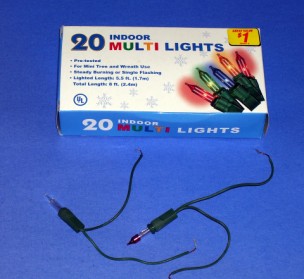
have around the house. One thing you will need is an
old string of miniature Christmas tree lights that no
longer works. The best kind is the type where the lights
continue to burn after one bulb goes out. This type of
string almost always has three wires running throughout
the string. It is an excellent source for wire,
bulbs and bulb holders.
CAUTION!
Always
use sharp objects such as knives or scissors with adult
supervision only! Hold any sharp point away from
your body, particularly your eyes.
Materials Needed:
Two "AA", “C” or "D" batteries; paper, tape (duct tape is
particularly good for this); two pieces of insulated wire,
each about 15 cm (6 in) long (This can be gotten from a bad
string of miniature Christmas lights. See Procedure below.);
knife or wire stripper; a small rubber band.
Procedure: If
you are going to get wire from the Christmas light string,
make sure that the string is unplugged! (Do we really need to say
this?) Start at the end of the string that plugs into the
wall. Using a pair of wire cutters or heavy duty scissors,
cut the plug off and throw it away. You will not need
it for any of these experiments. Do
not
plug it into a wall socket under any circumstances!
Carefully follow the wires to the first bulb on the
string. If you have a three wire string find the wire
that does not connect to the rest of the bulbs. It
should run the entire length of the string. Unravel
this wire from the other two, and cut it off. From
this piece, cut two 15 cm (6 in) pieces, and put the rest of
it aside to use later. This will give you plenty of
wire to complete all the experiments that follow.
Using a knife or wire stripper, carefully trim 1 cm (1/4 in)
of insulation from each end of both wires. If you are
using a hobby knife, cut around the insulation being careful
not to cut into the wire itself. You should then be
able to pull the insulation off the end of the wire with a
slight pull.
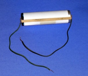
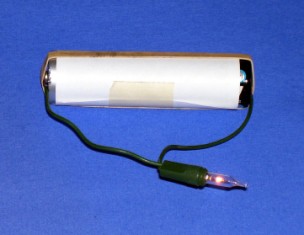
Place the two batteries end to end with the top of one
battery touching the bottom of the other battery.
Next, cut a strip of paper at least 27 cm (10 in) long, and
not quite as wide as the two batteries together. Roll
the paper tightly around the two batteries as shown in the
illustration, and tape the paper to hold it in place.
Hold the bare tip of one wire against the end of the bottom
battery, and tape it into place as shown.
Do the same thing for the tip of the top battery.
NOTE: once you have completed this step, you must not allow
the other ends of the two wires to touch as this will cause
the wires to heat up and the batteries to drain very
rapidly!
Finally, stretch the ru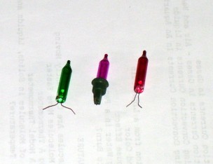 bber
band around the two batteries, making sure that it presses
the ends of both wires firmly against the batteries.
bber
band around the two batteries, making sure that it presses
the ends of both wires firmly against the batteries.
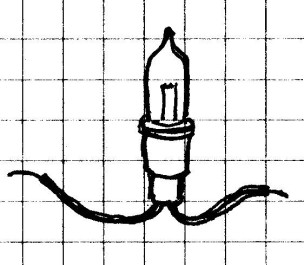
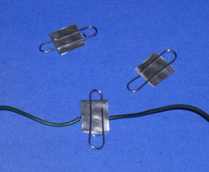
To test your battery holder, remove one of the Christmas
lights from the string. It should look something like
the middle bulb in the photo. You should see two very
small wires, one on either side of the light holder. Bend
the wires downward and gently pull the bulb from the holder.
When you do, you will be left with just the bulb as
shown on either side in the photo.
Carefully touch one wire on the battery holder to one
of the wires on the light. Touch the other wire from
the battery holder to the other wire on the light. The
two wires from the battery holder should not touch each
other.
What To Look For:
The bulb should light. Don't worry if it isn't very
bright. If it doesn't come on at all, make sure that the
paper is wound tightly around the batteries, that the bottom
of one battery touches the top of the other, and that the
wires and batteries are held firmly in place with the tape
and the rubber band. Then try again.
If the light still doesn't light up, your bulb may
be bad. Try another bulb.
What Happened:
When the light bulb lit, you created a simple circuit.
We'll find out what that means a little later.
Whenever you work with electricity, it is very important
that firm contact be made between all electrical
connections. If you had problems, it is likely that
you did not have good contact somewhere. Once you have
the battery holder working, put it aside for use in the
following experiments. Be sure not to allow the ends
of the wires to touch to prevent your batteries from running
down, or just remove them.
In some of the experiments that follow, you will need this homemade battery holder. It provides a safe 3 volt power source. In some cases, it will be easier to connect the wires to the batteries as you have done here, while in others, it will be easier to use the wires of the device you are trying to connect, as in the next experiment. Either way, be sure that the wires are firmly connected to the batteries on each end using tape and a good rubber band.
CAUTION!
Always
use sharp objects such as knives or scissors with adult
supervision only! Hold any sharp point away from
your body, particularly your eyes.
Materials Needed:
Christmas tree light string used above; homemade battery
holder.
Procedure:
Most
of the light holders on your string will have only two wires
coming from each light holder. Select one of these
holders and cut the two wires about 8-10 cm (3-4 in) from
the each end of the base. Then, trim 1 cm (1/4 in) of
insulation from the end of each wire as shown. Make
sure that you have a good bulb in your holder by using the
battery holder from the last experiment to test it.
When everything is working as it should, make three or
four of these using the same color bulb to use in later
experiments.
What To Look For: If the bulb is good
when you test it outside of the holder, it should light up
when replaced in the holder. If it doesn't, remove the
bulb and firmly plug it back into the holder and try
again. If it still doesn't light, you should try
another holder.
What Happened:
Again, all electrical connections must be tight. If
the bulb was loose, it would not light. Neither would
it light if one of the wires going into the bulb holder was
broken. A broken or loose wire going into one of
these holders is most often what makes these miniature light
strings go bad, so if you had trouble making one of these
bulb holders work properly, you should try another
one. Chances are, only one of the holders is
bad. You may also want to get a teacher or other adult
to help you.
Whether you realized it or not, you have already
made simple electrical circuits in the two previous
experiments. Now, you are going to make another one to
help you learn exactly what a simple circuit is.
Materials Needed:
Battery holder and light holder with bulb from above.
Procedure:
Place one wire from the bulb holder at one end of the
battery holder underneath the rubber band and tape the
wire in place. Do the same thing with the other end of
the battery holder..
What To Look For:
The light bulb should light up. If it flickers or
doesn't light at all, carefully check all your
connections. You may need to double wrap the
rubber band to insure that the wires are pressing firmly
against each end of the battery.
What Happened: The
wires, bulb and battery were all connected together in a
single continuous loop. This allowed electricity to
begin to flow through the wires from the battery, causing
the bulb to light. Notice that there had to be a
continuous loop for the electricity to flow. If you
broke the loop at any point by separating the wires anywhere
on the loop, electricity no longer flowed, and the light
went go out.
Procedure: Using a knife or wire stripper, cut four or five pieces of wire about 15 cm (6 in) long, and carefully trim 1 cm (1/4 in) of insulation from each end of the pieces.
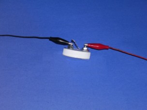
To connect two pieces of wire, press one bare end of each wire together, tear a small piece of aluminum foil, and wrap it around the two bare pieces as shown in the photo below.


Now try one or more of the following methods of connecting two wires:
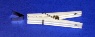
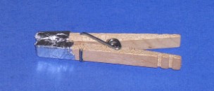
Another way of connecting wires is to place them between a folded piece of aluminum cut from a disposable aluminum pie pan and use the clothespin to clamp the folded aluminum piece and wires together. The advantage of this method is that you can reuse the aluminum strips.
CAUTION! Always use sharp objects such as knives or scissors with adult supervision only! Hold any sharp point away from your body, particularly your eyes.
Materials Needed: Small strip of corrugated
cardboard; disposable aluminum pie pan; paper clips; battery
holder from above; bulb holder from above; two connectors of
your choice from above; tape; two 15 cm (6 in) pieces
of wire from the light string.
Procedure:
Cut
a small strip of cardboard about 13 cm (6 in) long
and 3 cm (1 in) wide. Cut a strip from the smooth
bottom of the aluminum pie pan that is about 2 cm (3/4
in) wide and about 13 cm (6 in) long. Cut a
second piece from the aluminum pan that is about 2 cm (3/4
in) wide and 3 cm (1 in) long.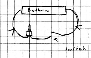
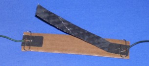
Use the paper clips to attach the two pieces of aluminum strips to the cardboard as shown. Bend the long strip upward near the connector. When you are ready to use the switch, place the bare end of each wire under the paper clip as shown.
To use your switch, connect one of the wires from your switch to one end of the battery holder. If you don't want to keep pushing wires into the battery holder, you can connect the wire from one side of the switch to one side of battery holder by using one of the connection methods shown above. Now connect one side of the bulb to the other connector on the switch and connect the other wire from the bulb to the other end of the battery holder. Check to see that your circuit now looks something like the diagram above.
NOTE: In this diagram, and some that follow, you will not see complete drawings of the switch, bulb, or battery holders. You will also not always see complete drawings of the connectors that hold the wire together, but when the directions call for you to use them, you should be able to figure out how they fit based on the diagram.
At this point, the bulb should not be lit. Press the long aluminum strip down so that it makes firm contact with the small strip. Does the bulb light? If not, check your connections.
What To Look For: With the two ends of
the switch not touching, the switch is "open" and
the light bulb will not light. However, when you
press down on the long strip of the switch so that it makes
contact with the short one, the switch is "closed."
The loop, or circuit, is now closed, and the
light bulb should light up. When you relase the long
strip, it breaks contact. This breaks the
loop and the light should go out again.
What Happened: The
word "circuit" means loop. A closed
loop or circuit allows electricity to flow, but an open
circuit will not. The switch you made, like all
switches, allows you to control whether the circuit (or
loop) is open or closed.
Materials Needed: The switch
from the previous experiment; light bulb and holder;
batteries; several small objects made from metal, wood,
paper; and plastic (such as coins, plastic bag, paper clip,
etc.), as well as any other small objects you want to test.
Procedure:
Put
together the circuit you made in the last
experiment. One at a time, place each object you
want to test between the two contacts on the switch.
Press down on the switch and notice whether the light
lights. Make a chart listing each object you test, and
beside that object, record whether or not the light bulb
lights.
What To Look For:
Notice which objects will cause the bulb to light and which
will keep it from lighting.
What Happened:
Bare
metal objects allowed the light bulb to light up, but
painted metal objects may not have. Paper, wood,
plastic or rubber objects would not allow the light to burn.
As you saw in the last experiment, electricity cannot move
through a circuit unless the loop is closed. Some
substances, such as metals, will allow electricity to flow
through them freely. They are called conductors.
Other objects, such as paper, wood, plastic and rubber, will
not allow electricity to pass through them. These
substances are called insulators, and they break the
loop that electricity must have for the bulb to
light.
Going Further:
Can
you find any non-metal substance that will allow the bulb to
light?
Materials Needed: Circuit from
the last experiment; another bulb with
holder; wire stripped at each end as needed,
Procedure:
Carefully observe the brightness of the bulb in the crcuit
made in the last experiment. Next add another light
bulb to assemble the circuit shown below. Press the
switch to light the bulbs.
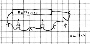
In what way, if any, does adding the extra bulb change the brightness of the first bulb?
Now change the circuit as shown.
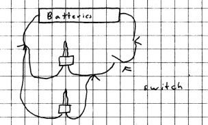
Parallel Circuit
What happens to the brightness
of the bulbs ?
What To Look For:
You should observe both bulbs become dimmer in the first
circuit, but in the second circuit, the brightness of both
bulbs should be about the same as the first bulb alone.
What Happened:
The first circuit is called a series circuit.
That is, it is a single continuous loop, with both bulbs in
the same loop. The second circuit is called a parallel
circuit because the two light bulbs are parallel to
each other and the power source, and are in two different
loops. Do you see the two different loops?
In the series circuit, the two
bulbs share the same loop and must share the available
electricity flowing though the circuit, so when both are on
the the same loop, each bulb is only half as bright.
In the parallel circuit, both loops are closed and
current electricity is able to move through them in the same
amount, so the two are just as bright as in the circuit with
a single bulb. However, since both bulbs in the
parallel circuit are able to draw full current from the
battery at the same time, the battery will be drained twice
as fast as it would with the two bulbs in series.
Going Further:
Try adding more bulbs in series, and in parallel, and see
what happens. Can you make a circuit that has bulbs in
series and in parallel? If so, what happens.
Also, in the parallel circuit, can you find a place to
insert the switch so that it will cause only one bulb to go
out when it is opened?
But wait, there's more. Be sure to
visit Current Electricity and Simple
Circuits - Part 2.