 The
Science Notebook
The
Science NotebookMagnetism, Magnets and Electricity - Pt. 2
The
Science NotebookHome Terms of Use Safety Contact Us Experiment Pages Downloads Supplies Useful Links!
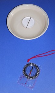
Materials Needed: Small bowl; steel needle
(or pin); magnet; compass; disposable foam coffee cup.
Procedure:
Magnetize
the needle or pin by stroking it with a magnet several times
just as you did with the nail. Cut the bottom from
a foam coffee cup leaving just a little bit of the
side, and make a small notch on each side of the bottom so
that the needle can rest on top of the circle without
moving. Place the needle or pin so that it rests in the
notches. Next, fill the bowl with water and carefully
float the needle and foam in the bowl. Allow the
needle to settle down.
Place the compass a few feet away and allow the compass
needle to settle down as well. Make sure the magnet
you used isn’t near either the compass or the magnetized
needle.
What To Look For: In
which direction is the needle pointed? What about the
compass?
What Happened: You
have already learned that the needle in a compass is really
a small bar magnet. So is the magnetized needle.
The compass needle is able to turn freely. The
magnetized needle is able to turn freely because it floats
on the foam circle. However, because the
lid is completely free to float, it may drift to the side of
the bowl, and so would not make a very good compass for
practical use. But you can use what you have learned
so far to make a better one...
The compass you will make in this experiment is
similar to the one you just made, but with one big
improvement. In the last experiment, you probably
noticed that the cup bottom and needle would move to the
edge of the bowl and it could no longer turn freely.
You can fix that by adding a straight pin, a piece of a
soda straw and a little modeling clay to make a pivot for
your compass.
Materials Needed:
Small bowl; steel needle (or pin); magnet; compass;
Styrofoam coffee cup; modeling clay; straight pin; soda
straw.
Procedure:
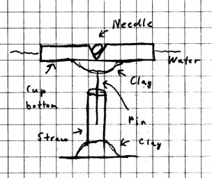
Cut
the bottom from a foam coffee cup and prepare it just
as you did in the last experiment. From the same side
as the notches, push the straight pin through the center of
the cup bottom and push it all the way through except for
the head. Place just a little modeling clay around the
pin on the underside to hold the pin in place. Next,
cut a 3 cm (1 in) piece from the soda straw. Then,
place a small lump of clay in the bottom center of the
bowl. Place one end of the straw into the lump of clay
so that the straw is sticking straight up as shown.
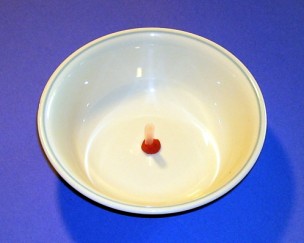
Magnetize the needle or pin just as you did before.
Place the needle or pin in the notches. Next, fill the
bowl with water so that it completely covers the straw and
carefully place the foam bottom and needle over the
straw so that the pin coming from the underside of the
bottom goes inside the straw. There should be
just enough water in the bowl to allow the bottom and
needle to float freely. The pin inside the straw
will act as a pivot to prevent the needle and cup
bpttom from drifting away
Allow the needle to settle down and check the direction of
the needle with that of a compass as you did in the last
experiment. Now turn the cup bottom a couple of turns
and let it go. What happens?
What Happened: Just
as a real compass needle turns about on a pivot, the needle
of the homemade compass was able to turn around freely but
was prevented from floating to the side of the bowl by the
straw and pin pivot. While you couldn’t very well take
this compass with you to the woods or on a ship, you could
use it to perform the other experiments in this book that
call for you to use a compass.
Going Further: Can
you use what you have learned to make a more
usable compass?
If you tried the experiment using tha bar magnet as a compass on the Magnetism 1 page, you already know that a bar magnet suspended and alllowed to swing freely will act as a compass. (If you missed that one, you can click HERE to view it.) In the experiments above, you have seen the same thing with an induced magnet allowed to move freely in water. In this experiment, you will use an induced magnet suspended in air as a compass.
CAUTION! Always use sharp objects such as knives or scissors with adult supervision only! Hold any sharp point away from your body, particularly your eyes.
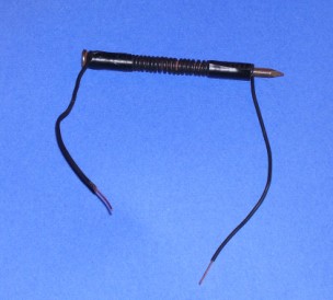
Materials Needed: Steel clothes
hanger; (You can test it with a magnet.); wire cutter;
permanent magnet; compass; nylon fishing line or string;
fishing swivel; paper, scissors; tape; empty box or
other support.
Procedure:
Have an adult to cut a 30 cm (12 in) section of wire
from the bottom of the clothes hanger. Use the
permanent magnet to make an induced magnet of the clothes
hanger wire as described in THIS
EXPERIMENT on the Magnetism 1 page. (Will open
in a new tab or window.)
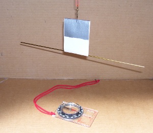
Cut a piece of paper 3 cm (1
in) by 6 cm (2in). Tape the two 3 cm (1 in) ends
together to form a teardrop shape. Punch a small hole
in the middle of the taped part almost at the top.
Hook the fishing swivel through this hole. Tie a 30 cm (12
in) piece of fishing line or string to the other end of the
swivel. Tape the other end to the inside of a
cardboard box as shown. Slip your wire
induced magnet through the paper loop and balance
it. Once the magnet is balanced, let it go until it
stops swinging.
While you are waiting for the magnet to stop swinging, move
the compass some distance away from the hanging magnet, and
let it settle down as well. Note the direction in which the
compass is pointing. Now note the direction the wire
magnet is pointing.
(NOTE: If you don’t have a fishing swivel, you can simply
tie your line or string directly to the paper.
However, without the swivel, the magnet may spin around
a bit, especially if you had to use string, and you may need
to give it a few minutes to stop swinging. )
What To Look For: If
all was done properly, the wire magnet should be
parallel to the compass needle. You should see
that both the magnet and the compass line up north to south,
and the magnet behave just like a compass.
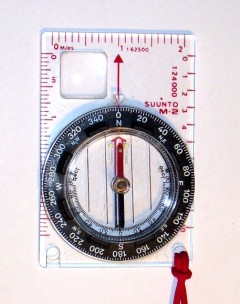
Materials Needed: A compass.
Procedure:
Place
the compass on a table or other flat surface and allow the
needle to stop swinging. Carefully turn the compass so
that the end of needle which points north is lined up with
the “N” on the compass rose or the direction ring. The
compass rose is the card under the needle with the
directions printed on it. The direction ring is a ring
around the edge of some compasses that may be turned.
If your compass has a rose, it may look like a star, or it
may simply be a series of numbers and marks that show N, S,
E, and W, or go from 1 to 360, or both.
What To Look For:
As
you have already seen, the compass needle is a small bar
magnet. Unless it is very close to another magnet or a
large object made of iron or steel, it will line itself up
in a north-south direction. By lining up the needle
with the “N” on either the compass rose or the direction
ring, you can not only tell which direction is north, you
can also identify all the other directions as well.
What Happened:
Scientists believe that the core of the earth is made up of
a mixture of iron and nickel metals. The outer part of
this core is thought to be liquid, while the inner core is
believed to be solid. In a way that is not completely
understood, the core behaves like a giant magnet with a
north and a south pole. The poles are located many
miles below the surface of the earth, near the actual north
and south poles of the earth. The actual poles are
called the geographic poles. As you have already seen, any
magnet, if left to turn freely, will align itself with the
earth’s magnetic field. The north pole of the magnet
will always point north, while the south pole will always
point to the south. However, since the magnetic poles
of the earth are not located at exactly the same points as
the geographic poles, a compass may or may not point exactly
north, depending on exactly where the compass is located.
Going Further: Look
up compass in an encyclopedia or online to learn more about
how it works.
We said that electricity and magnetism were
related. In this experiment, you will see how
electricity can be used to make a magnet.
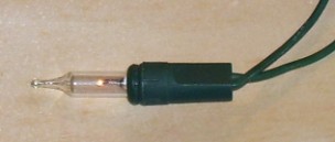
Materials Needed:
Insulated copper wire (You can use wire from an old Christmas light string
or or almost any other covered wire); iron nail (not
galvanized); homemade
battery holder with 2 AA, AAA, C or D cells; two wire
connectors of your choice; homemade switch (This is optional, but
will make the experiment much easier to do.); wire from your
circuit experiments; small staples or paper clips.
Procedure:
Starting
about 5 cm (2 in) from the end of the insulated wire, wind
about 30 turns around the nail. Leave the same amount
on the other end. (If the wire doesn’t want to
stay in place, you can tape it down by wrapping a little
tape around each end. Carefully strip about 1 cm (½
in) of the insulation off of each end of the wire.
Next, assemble the circuit shown below. If you are
using the switch, assemble it like this:
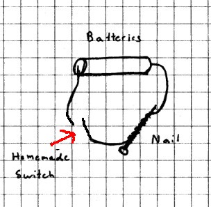
If you are not using the
switch, leave a gap between the wires where the switch would
go.
Press the switch (or touch the two wires where the
switch would be together), and bring the coil near a few
loose staples. What happens?
IMPORTANT! Do not leaves the switch closed or the
wires connected for more than a few seconds as this will
quickly drain your batteries! Remember, this is a “short” circuit!
Open the switch or disconnect the wire. Now what
happens to the staples?
What Happened:
When
the switch was closed, electricity began to flow through the
wire. The flow of electricity through the wire created
a magnetic field that caused the coiled wire and nail to
behave like a magnet. However, when you opened the
switch or disconnected the wire, electricity could no longer
flow and the magnetic field disappeared. (You may see
that the nail still acts as a magnet even after you open the
switch or disconnect the batteries. We’ll see why in
just a little bit.)
When a magnet is made by electric current flowing through a
wire it is called an “electromagnet”. However, you may
remember that when you send an electric current through a
wire that this creates a “short” circuit that will quickly
drain the batteries. That’s why you don’t want to
leave the batteries connected for too long!
Going Further: What
effect does adding more turns of wire have on the strength
of the electromagnet? How about fewer turns?
NOTE: You will use this same setup to do the next
experiment.
Materials Needed: Setup from the last
experiment.
Procedure: Turn
the electromagnet back on by closing the switch or
reconnecting the wires for a couple of seconds. Open
the switch or disconnect the wire so that current cannot
flow. Next, unwrap the wire from the nail.
Now bring the nail near some staples. What happens?
What To Look For:
The staples should be attracted to the nail, although the
attraction may be very weak.
What Happened: When
the electricity flowed through the wire, it not only created
a temporary magnetic field, it also caused the iron atoms to
line up and create a weak magnetic field. When current
stopped flowing, the iron atoms remained in place and a very
weak magnet was created. This is another example of
induced magnetism, but in this case, electricity is used to
create the field instead of a permanent magnet.
Going Further: Can
you strengthen such a magnet by leaving it connected
longer? (Don’t try this for too long. Remember
this is a “short” circuit which will drain your batteries
very quickly!) Can you demagnitize this magnet using
heat or by rapping the nail?
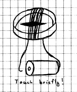
Materials Needed: Insulated
copper wire; compass; one AA, AAA, C or D cell.
Procedure:
Wrap
four or five turns of wire around the compass. Strip
the insulation off the ends of the wire. Turn the
compass so that the wire is lined up with the compass
needle.
Hold one end of the wire to the bottom of the cell. At
the same time, touch the top of the battery with the other
bare end for just a second. What happens?
What To Look For:
The needle should move from underneath the wire.
What Happened: You
have already seen that a magnetic field is created when a
current passes through a wire. The compass needle,
which is a magnet, responds to that magnetic field by lining
up with it. This setup can be used to detect small
electric currents. It also helps us to understand how
a motor works, as we will see later.
Going Further: What
happens if you use fewer turns of wire? What happens
if you simply place a wire with electricity flowing through
it across the compass?
In the last experiment, you actually made a
galvanometer, which is a simple device used to detect
small electric currents. In this experiment, you
will make a more permanent and sensitive
galvanometer.
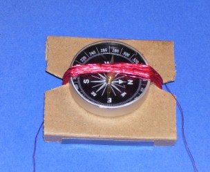
Materials Needed:
Compass; magnet wire; corrugated cardboard; tape.
(Magnet wire is thin copper wire that is coated with
enamel. It is available from Radio Shack®. If
you can’t find magnet wire, you can use insulated wire, but
it will be a little thicker.)
Procedure: Cut a
small rectangle of cardboard. The shorter side should
run along the corrugations, and should be about 1 cm (½ in)
longer than the compass. The longer side should be at
right angles to the corrugations and should be about 2 cm (1
in) wider than the compass.
Next, fold the cardboard along the corrugations about 1 cm
(½ in) on each side. Cut a small “v” shaped notch into
the other two sides in the center. Tape the compass to
the top of the cardboard with the “N” and “S” of the compass
rose lined up with the notches.
Leave about 30 cm (1 ft) of wire, and wind 50 turns
around the notches. When you have finished winding,
leave about another 30 cm (1 ft). You can tape the
wire coil on the underside to hold it in place. Place
another piece of tape from one side of the cardboard to the
other on the underside to make the galvanometer
steady. Strip about 1 cm (½ in) insulation from each
end of the wire.
To test your galvanometer, line it up so that the wire coil
is lined up with the needle. Touch the wires to the
ends of a cell, and observe the needle. Reverse the
wires. What happens?
What Happened: When
you touched the wires to the cell terminals, the needle
swung out from under the wire and probably went at right
angles to the wire. The swing may have been strong
enough to cause the compass needle to spin. When you
reversed the leads, the needle again swung out, but this
time in the opposite direction. The magnetic field
created by the electric current is at right angles to the
flow of the current through the wire.
Going Further: Find
a battery that appears to be “dead” and test it with your
galvanometer. You may be surprised to find that it
will deflect the needle at least a little. Even though
the dead battery may not be producing much current, the
galvanometer can detect even the small amounts of current
being produced.
This project began as a motor is based on the
“Beakman” motor from the TV show, “Beakman’s World”, and
works on the same principle. However, this version
uses wood screws instead of paper clips for support to
make the motor a little more durable. It also
takes a hint from a motor experiment developed by Home
Science Tools, using ink from a permanent marker as
an insulator. You can also add a switch to
prevent the battery from accidentally running down.
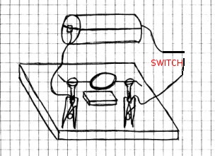
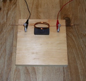
Materials Needed: Small piece of wood, about
6" square; 2 2x10 flat head (not Phillips) screws; 2
clothespins; insulated wire (or you can substitute two clip
leads for the clothespins and wire as shown in the photo); homemade switch (optional, but a good
idea); D cell; small rectangular magnet (Radio Shack® #
64-1877 or similar); 22 gauge magnet wire; rubber band;
tape; aluminum foil; toilet paper tube; sand paper;
permanent marker.
Procedure:
Starting
about 9 cm (3 in) from the end of the magnet wire, wrap 7
turns of wire around the toilet paper tube. Measure
off another 9 cm (3 in) and cut the wire. Carefully
slip the wire off the paper tube while holding the wire
turns together so that they don’t come loose. Loop the
two ends of the wire around the coil tightly a couple of
times to secure the coil as shown in the diagram.
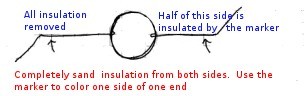
Next, using sandpaper, completely remove the insulation
off of both ends up to the edge of the coil. This next
step is important! Placing the coil on a flat surface,
use the marker to completely cover one side of the wire
only.
Screw the two wood screws into
your board 12 cm (4 in) apart as shown. You should be
careful to screw them in as straight as possible, and you
only need to screw them in enough to hold them securely for
the time being. Both should be screwed in to the same
depth, and the slots on both heads should line up in a
straight line.
Cut a 15 cm (6 in) piece of insulated wire and remove ½ cm
(1/4 in) of insulation from each end. Tape one end over one
end of the D cell. Tape the wire from one end of
the homemade switch over the other end, and secure the wire
to the cell using a rubber band, just as you did for the homemade
battery holder.
Fasten the free wire ends coming from the D cell to the one
of the screws near the base by wrapping the
bare wire with foil and clamping the wire and foil
to the screw with a clothespin. If you want to
add a homemade switch; insert it as shown in
the diagram,
While making sure that your switch is off, place the ends of
the coil into the slots on the screw heads. Give the
coil a slight spin to make sure it spins freely. If
not, adjust the screws and the coil as required. Then,
center the magnet directly underneath the coil, and spin the
coil. The coil should not touch the magnet as it
spins. A gap of about ½ cm (1/4 in) inch is
good. If you need to raise or lower the coil, adjust
the screws up or down as needed.
Once you’ve adjusted everything, close the switch and
give the coil a spin. It should begin to turn on its
own. If not, try spinning the coil in the opposite
direction. If it still doesn’t spin on it’s own,
slowly turn the coil until you see it attracted to the
magnet. You may need to shift the magnet around a
little. If it is not attracted to the magnet somewhere
along the way, check your sanding to make sure you removed
the insulation properly. If it doesn’t spin easily,
you may need to readjust the coil so that it
does. Once you have the motor working properly,
you can bend the wires on each end to keep the motor from
flying off of the screw heads.
What Happened: As
the coil rotated, the side that was half insulated with
marker ink turned so that the half with no
insulation came in contact with the metal screw making
a complete circuit. This created an electromagnet
which was attracted to the bar magnet below it. When
the coil was pulled down to the magnet, the insulated side
of the wire touched the screw head which broke the
circuit. Inertia kept the coil spinning until the bare
wire contacted the screw and the circuit was completed
again. The coil was again attracted to the
magnet. As long as the battery was hooked up, the
cycle kept repeating and the motor continued to spin.
Going Further: There
are many ways of experimenting with this motor.
Changing the shape of the coil or the number of turns of
wire used, or adding another cell are just a few of the
things you can try.
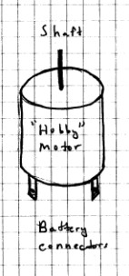
You have seen how a motor works by creating an
electromagnet that is switched on and off. Hobby
motors, like those used in model cars and other toys, have
electromagnets that switch on and off. These motors
are available at Radio Shack ® and at many hobby
shops. With the help of an adult, you may even be
able to salvage one or two from old toys.
Materials Needed:
1.5 to 3 volt hobby motor (Radio Shack ® #273-223 or
equivalent); two alligator clips (Radio Shack ® #270-374 -
These are optional, but very helpful); insulated wire;
aluminum foil; 2 AA, C or D cells; homemade
battery holder; homemade switch; small iron or steel
object such as a pin or staple.
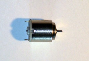
Procedure: Examine
the hobby motor. You should see two small metal tabs
with holes in them. There are the “terminals” where
the wires are connected to the motor. Move your small
iron or steel object around the outside of the motor.
Is this object attracted to the motor at any point?
Remove ½ cm (1/4 in) of insulation from each end of a 15 cm
(6 in) piece of wire. Make a homemade battery holder
using this wire and the two cells. Connect one of the
wires of the homemade switch to one end of the battery
holder. Make sure the switch is open. Connect
the other switch wire to one of the terminals on the motor
by inserting the bare wire into the hole, wrapping it with a
bit of aluminum foil, and clamping it in place with an
alligator clip. If you don’t have an alligator clip,
strip about an inch of insulation from this wire, run it
through the hole, twist tightly and wrap a bit if aluminum
foil around the wire. Squeeze the foil tightly. Do the
same thing with the wire from the other side of the battery
holder. Hold the motor firmly and close the
switch.
What To Look For: The
motor
should begin to run. If it doesn’t, carefully recheck
all of your connections.
What Happened: You
should have discovered that some part of the motor appears
to be magnetic when you held the iron or steel object close
to the motor. This is because most hobby motors have
one or more magnets inside. The magnets inside the
hobby motor serve the same purpose as the magnet on the
homemade motor.
By connecting a battery (two cells) to the motor, you
assembled a circuit that provided electricity to several
electromagnets in the motor. Having several
electromagnets allows the motor to spin very rapidly.
As we will see in the next experiment, something else very
interesting is going on.
Going Further: Notice
the
direction in which the motor is spinning. What happens
if you reverse the wires on this motor?
When a magnet passes through a coil of wire, the
magnetic field produces an electric current. This should
not be surprising, since we have already seen that
electricity flowing through a coiled wire produces a
magnetic field. Remember the galvanometer? And
since a motor has one or more coils which are turning past
one or more magnets, it should not surprise you that a
motor may also be used to generate electricity.
Materials Needed:
All the materials from the previous experiment; a second
hobby motor; a small piece of wood, about 15 cm (6 in)
square; a light and holder from the Christmas
light set; modeling clay; an unused eraser from a new
pencil; aluminum foil; two additional alligator clips
(optional); a straight pin.
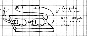
Procedure: Assemble
the motor circuit from the last experiment.
Using a pair of pliers, pull an eraser from the end of a new
pencil. Push a straight pin through the center from
the top of the eraser all the way through the bottom.
Keep it as straight as possible. Remove the pin.
Push the shaft of your second motor into the hole at one end
of the eraser and slide it about halfway through the
eraser. Push the shaft of the first motor through the
other end of the eraser so that the two shafts are
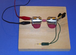
joined. Place both motors on the board and brace them
with four pieces of modeling clay as shown.
Next, close the switch to test the setup. The friction
between the eraser and the shafts should cause the shaft of
the second motor to turn when power is connected to the
first motor. You may need to adjust the position of
your motors and their braces so that the motors turn as
smoothly as possible.
Finally, attach the two ends of the lamp holder with lamp to
the two terminals of the second motor in the same way as you
attached the battery and switch to the terminals of the
first motor. Now turn on the first motor. What
happens?
Be sure to leave this setup in place for the next
experiment.
What To Look For:
The lamp should light. If it does not, check it’s
connections to the second motor. Also, check your bulb
to insure that it is not burned out and try again. Pay
very close attention to the brightness of the bulb for the
next experiment.
What Happened: The
second motor is not electrically connected to the circuit
powering the first motor. However, as the first motor
spins, it causes the second motor to spin since the shaft of
the first motor is turning the second due to the connected
shafts. As the second motor spins, it’s coils pass
through magnetic fields created by the permanent magnets
inside the motor. This produces electricity that
lights the bulb. The second motor is being used as a
generator.
Going Further: Now
that you know what is happening, perhaps you can come up
with other ways of generating electricity. Connect a
light to a single motor with another eraser fastened to the
shaft. Turn a bicycle upside down and have a friend turn the
pedals while you place the side of the shaft of the motor
against the outside of the turning wheel. Can you
cause the shaft to turn by friction and produce enough
electricity to light the bulb?
In the last experiment, you made a small
generator. Now, you’ll get some idea of just how
efficient your generator actually is.
Materials Needed:
(For the most accurate results, all of these materials
should be from the last experiment.) Light bulb and
holder; switch and battery holder with batteries used to
power the first motor; two clothespins; aluminum foil;
alligator clips (optional) .
Procedure:
You
should have observed the brightness of the bulb as lighted
by the generator in the last experiment. If you didn’t
notice it before, connect the light to the generator again
and observe the brightness of the bulb.
Now, using the aluminum foil and clothespins or alligator
clips, connect the light directly to the battery holder and
observe its brightness. Is there a difference?
What Happened:
Your two cell battery should be producing about 3 volts when
it powers the motor that turns the generator. However,
the output of the generator will be somewhat less,
since some of the energy used to power the first motor is
lost as heat or friction, and additional energy is also lost
due to friction created by the spinning of the second
motor. Therefore, not all of the energy will go into
generating electricity. Another way of saying this is
that the generator is not 100% efficient.
When you connect the light directly to the battery, you
don’t have these losses. All of the available energy
from the batteries goes to lighting the bulb so it is
brighter.
Going Further: If
you are looking for a good science project, you might want
to compare the efficiencies of a generator powered by two
cells used to light a bulb, and two cells which light the
bulb directly.
Start with four fresh cells and using two of them, construct
a generator as before. Using the other two cells,
construct a light circuit using the same arrangement as in
this experiment. Make sure you use the same size bulbs, and
keep everything in the two setups as nearly alike as
possible. Compare the brightness of the two bulbs over
time. What do you conclude? You may also want to
compare how long two batteries will last when used to
power the generator to light the bulb versus how long two
batteries will last lighting the bulb directly.
If you have gone through all the electricity and
magnetism pages, congratulations! If not, cruise on
over to the Experiments page. There you'll find
links to these pages and much, much more!